

Operation Video
Extrusion Assembly
The Extrusion Assembly controls filament extrusion and retraction. It consists of the Extruder Front Cover, Extruder Gear Assembly (active gear), Extruder Lever (idler lever), Toolhead Filament Cutter, and other related components.
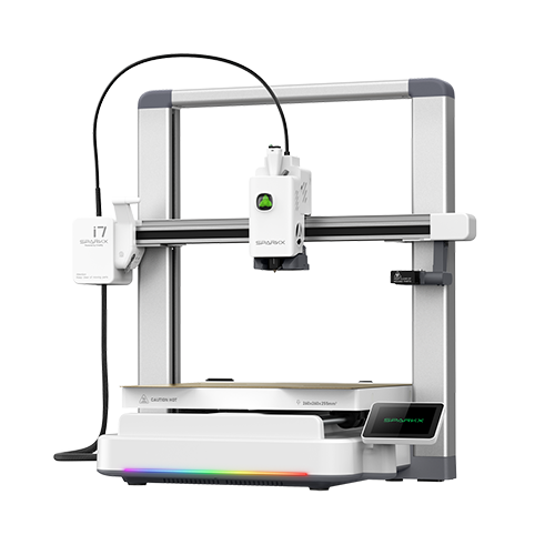
This guide explains how to replace the Extrusion Assembly on i7 series printers.
Replacement Timing
The Extrusion Assembly is damaged;
Replacement recommended by the Creality after-sales team.
Required Tools
- H2.0 Hex Wrench
- Tweezers
Safety Preparation
Turn off the printer and unplug the power cable.
Before starting, check the temperature of the Hotend and Heated Bed. Avoid operating while hot to prevent accidental contact with high-temperature components.
Pre-Operation Step
Perform a filament retraction procedure in advance to ensure the Extruder is free of filament, making disassembly easier.
Remove the Old Extrusion Assembly
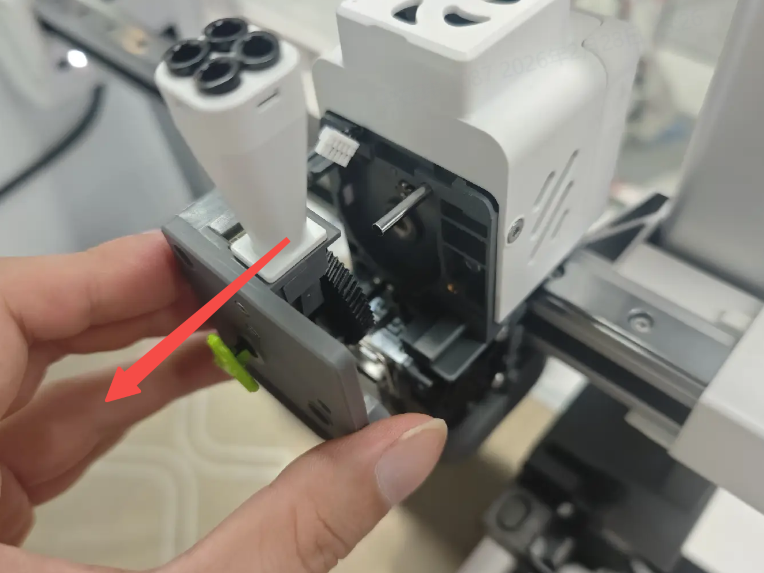
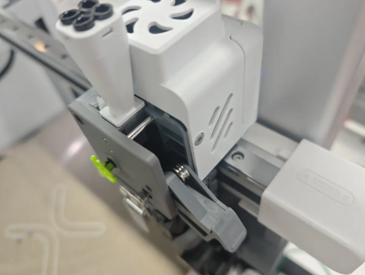
Remove the PTFE Tube from the Toolhead Manifold by pressing down the fitting and gently pulling out the tube.
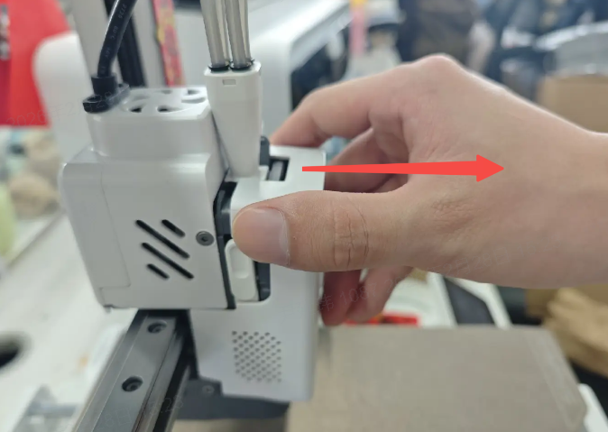
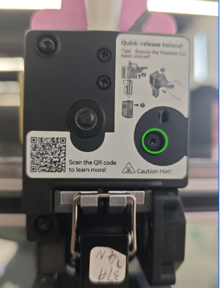
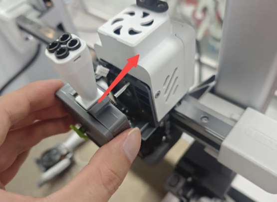
Remove the Toolhead Front Cover to expose the main Toolhead Assembly, then remove the Toolhead Rotating Ornament.
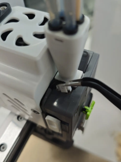
Use tweezers to disconnect the top terminal that connects to the Filament Sensor.
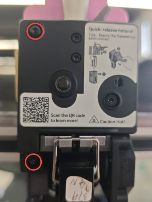
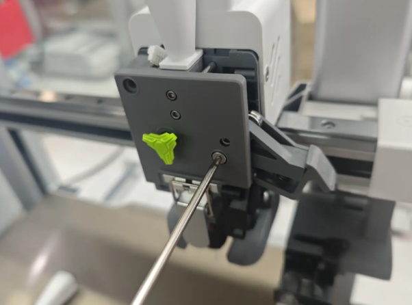
Open the Extruder Lever, then use the H2.0 Hex Wrench to remove the screws shown in the diagram, and take off the Extruder Lever.
Continue using the H2.0 Hex Wrench to remove the screws securing the Extruder Front Cover. Once removed, the internal Extruder Gear Assembly (black gear) will be exposed and can be taken out together.
Install the New Extrusion Assembly
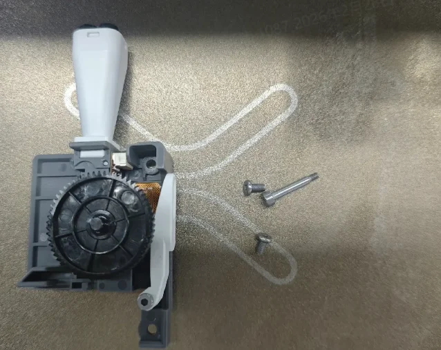
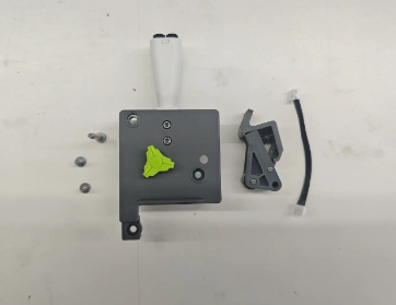
Prepare the new Extrusion Assembly. Take care not to lose small components.
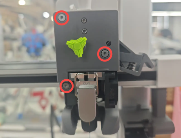
Reinstall the new extruder front housing and the driven pulley wrench to their original positions.Ensure that the gear shaft is aligned with the screw holes. A long screw can be used to assist with positioning and alignment.
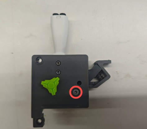
Tighten the three screws to secure the assembly.
Close the Extruder Lever and reconnect the top terminal.
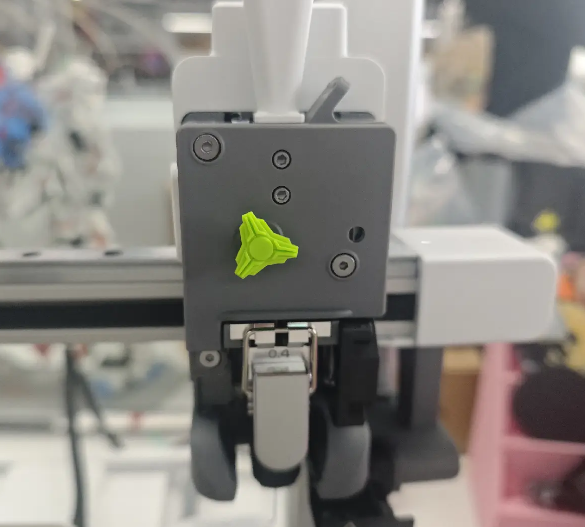
Reinstall the Toolhead Rotating Ornament and Toolhead Front Cover. After reinserting the PTFE Tube, the Extrusion Assembly is ready for use.